UART PIC to Argon Tutorial
UART PIC to Argon Tutorial
Objectives
Getting familiar with UART on both PIC and Particle platforms. In this tutorial, you will set up the PIC as a black box that will respond to various inputs from the Argon. Utilizing the USB serial bus on the Argon, we can verify the project at the end.
Resources
Procedure
-
Configure the PIC Device
First you need to create a new project and set it up for your device and how you plan on programming it. For the Curiosity Nano, it will be a PIC16f18446 programmed with the XC8 compiler and the curiosity nano hardware tool.
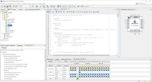
Hopefully MCC opens automatically and brings you to the System Module page by default. If not, click the MCC button (
 ) at the top to initialize it.
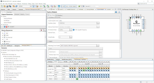 Figure
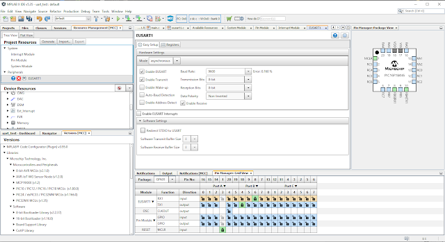
On the left side of the screen, find the Device Resources and select EUSART1 to add it to the project.
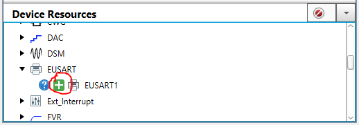 MCC View
For most applications, default settings should be fine. For convenience, I will move the RX and TX pins to RB6 and RB4 respectively.
 Figure
Click Generate at the top left by Project Resources.
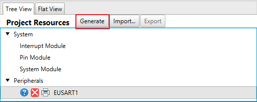 Figure
Open up the EUSART1.h header file under the project files. This will have all of the MCC generated functions that can be called to do whatever is needed.
 Figure
You will want to make sure to call the initialize function first. As a general rule of thumb, you will want to check if RX is ready before you read data and check if TX is ready before you send data. For this tutorial, I will say that if the PIC receives the character ‘a’, it will respond with a 1. If the PIC receives a ‘b’, it will respond with a 2. For all other inputs, it will not respond. Take this as an opportunity to try to read some of the provided documentation and see if you can figure out a solution before continuing on.
This is the code that I created for this project:
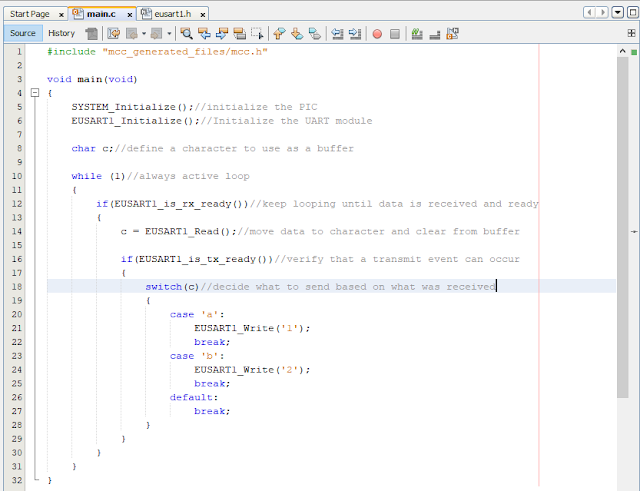 Figure
Click the Hammer button (
 ) to compile the project. If you see “Build Successful”, then you can flash the program to the microcontroller by clicking the Run main project button (
 .)
.) -
Configure the Particle Device
Configure your Particle device to connect it to WIFI and connect to it through build.particle.io
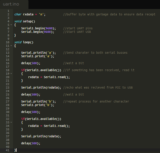
Particle follows the same language reference as arduino with one small difference. The Serial only applies to the usb port. Serial1 will do the same thing, but only applies to the RX and TX pins.
The particle device should be programmed to send out a character and see what response is received, printing both to a usb serial interface. Repeat this process to verify all parts of the PIC code.
Here is the code that I created: It’s not great but it achieves the needed goals. Generally, delays should be avoided as they lock up the processor from doing other things for the duration.
 Figure
This code can then be flashed to the Particle device using the Flash (
 ) button.
 -
Connecting the Devices.
Power should be connected to both the PIC and the Particle devices.
RX and TX can be connected between the devices making sure to cross the connection. RX goes to TX and TX goes to RX. The transmit of one device will be received by the other.
The Particle device should be connected to a computer via USB.
Open a PuTTY terminal to the Serial port of the Particle device. You could also use the Serial Monitor of the Arduino IDE as both will do the same thing. Here you should be able to see the characters being printed by the Argon. After each ‘a’, a 1 is received and after each ‘b’, a 2 is received. This shows the devices are communicating properly.
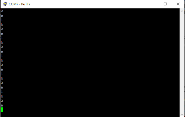 Figure
Tutorial written by Mykol Reklaitis, March 2020