Pushing PCB changes back to a schematic in Cadence
Why would I need to back annotate a design?
If you make changes to your design while in PCB Editor (for example, swapping a footprint), you must back annotate (meaning, push changes) from the PCB design back into your original schematic. By doing this update, future changes to the schematic can be forward annotated (meaning, pushed forward) to your PCB design without having to start over from scratch.
How do I back annotate a design from PCB Editor to Design Entry CIS?
-
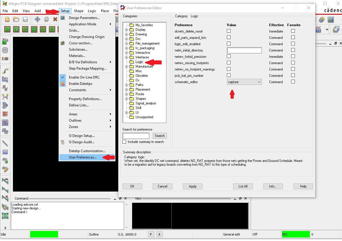
In PCB Editor, choose Setup > User Preferences… and click on the Logic folder. The User Preferences Editor window will appear (see Figure 1).
Figure 1: User Preferences Editor window with Logic folder selected -
Under the Logic folder, set schematic_editor to capture (see Figure 1, above). Close the User Preferences Editor.
-
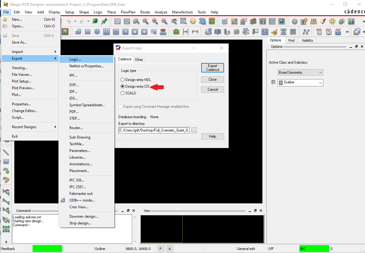
Choose File > Export > Logic…. The Export Logic dialog box will appear. (see Figure 2).
Figure 2: Export Logic dialog box -
In the Export Logic dialog box, select the Cadence tab and choose the Design entry CIS option under “Logic type” (see Figure 2, above). If the path under “Export to directory” does not point back to the directory your design is stored in, click the “…” button and change it.
-
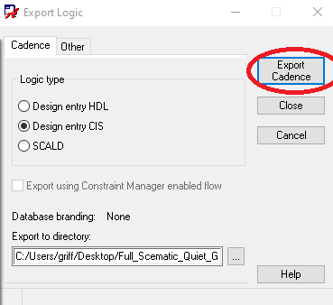
In the Export Logic dialog box, click the “Export Cadence” button (see Figure 3). You are now finished exporting the design from PCB Editor, but still need to import the design changes into Design Entry CIS.
Figure 3: Export Cadence button in the Export Logic dialog box -
Open your project in Design Entry CIS.
-
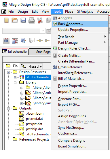
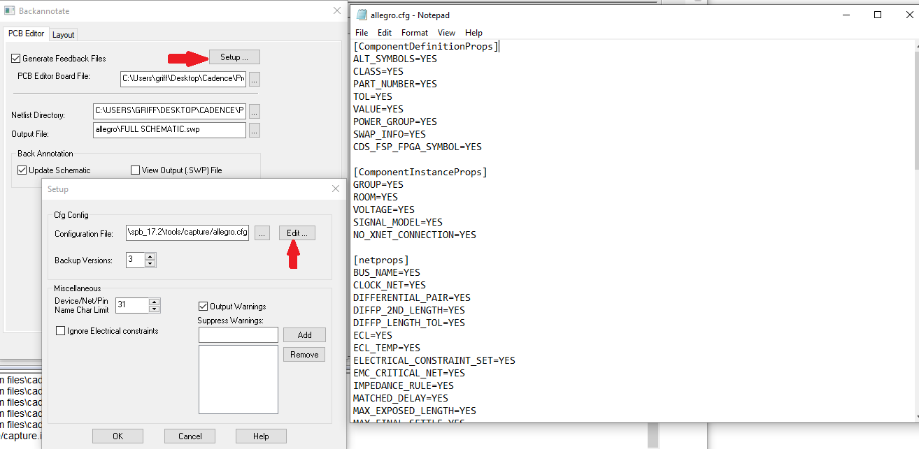
In Design Entry CIS, go to the “Project Manager” window and select the project icon. Choose Tools > Back Annotate… (see Figure 4). The Backannotate dialog box will open (see Figure 5). If you want to make any changes to what is imported, click the “Setup…” button and edit the allegro.cfg file (not recommended for most users) (see Figure 5).
Figure 4: Project Manager and Back Annotate…Figure 5: Backannotate dialog box and setting up the path8. Click “OK” to complete the back annotation.
Based on a tutorial written by Seana O’Reilly and updated by Griffin Puggie
