Exporting Gerber files from Cadence PCB Editor
What is a Gerber file?
A Gerber file (also known as artwork) is a 2-D graphical representation of a single layer of a PCB. A typical design will have individual Gerber files for each layer (e.g., top copper, bottom copper, top silkscreen, bottom silkscreen, top soldermask, bottom soldermask) of a PCB.
What is a drill file?
A drill file (also known as a NC Drill file) stores both the specific sizes and types of drill bits that will be used in manufacturing a PCB in addition to the specific coordinate locations where each hole must be drilled. Our equipment uses files that are in Excellon format.
You need both Gerber files for each layer and a single drill file in order to successfully submit your design for manufacturing.
Video Walkthrough
How do I export Gerber files from Cadence?
-
Open your PCB layout in Allegro PCB Designer
-
Choose “Manufacture > Artwork…” The Artwork Control Form window (see Figure 1) appears.
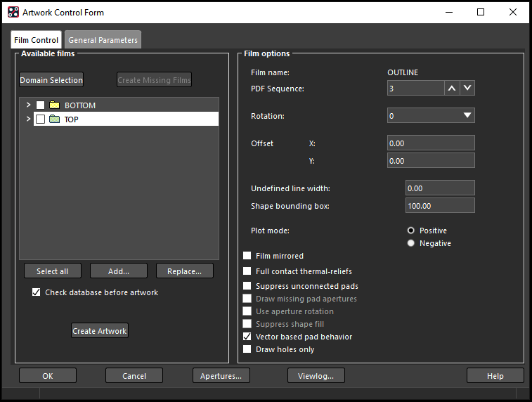 Figure 1: Artwork window
 -
Next, a board outline must be added. Right-click on the TOP folder and choose “Add Manual” (see Figure 2).
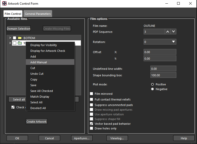 Figure 2: Right-click on TOP and choose “Add Manual”
 -
Enter a film name of OUTLINE and click “OK” (see Figure 3).
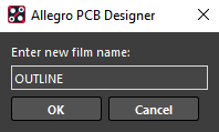 Figure 3: Film Name window
 -
Expand OUTLINE folder and right click on “BOARD GEOMETRY/DESIGN_OUTLINE” and select add.
 Figure 3.5: Subclass Selection window
 -
In the Subclass Selection window (see Figure 4), expand the BOARD GEOMETRY folder and check the box next to DESIGN_OUTLINE. Click “OK”.
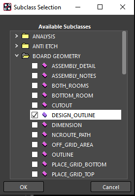 Figure 4: Subclass Selection window
 -
Select the OUTLINE checkbox (see Figure 5). Make sure in Film options that “Film name: DESIGN_OUTLINE” appears (if it does not, select the OUTLINE checkbox again). Set the Undefined line width to 0.1.
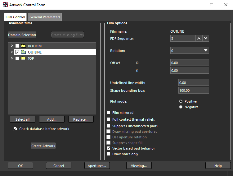 Figure 5: Artwork Control Form
 -
If you have an anti-etch (rubout), you will need to add it to the layer that you put it on. Click on the down arrow under the layer folder(s) that you added it too. Then, right-click on the items in the folder and select Add (see Figure 6).
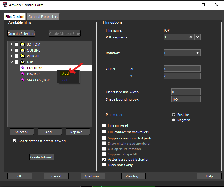 Figure 6: Add anti-etch layer
 -
Then, expand the anti-etch subclass folder and select the box next to the layer you are adding it to (see Figure 7). Repeat this process for each layer that you have an anti-etch on.
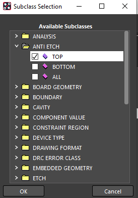 Figure 7: Adding the anti-etch layer to the top
 -
Click the “Select all” button to output all of the layers
-
Click “Create Artwork” to export the Gerber files
-
Click “OK” to return to the layout
How do I export solder mask files from Cadence?
See the Exporting Solder Mask Layers from Cadence PCB Editor tutorial
How do I export drill files from Cadence?
-
Open your PCB layout in Allegro PCB Designer
-
Choose “Manufacture > NC > NC Drill…” The NC Drill window (see Figure 6) appears.
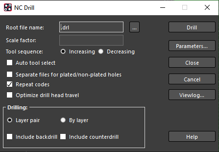 Figure 6: NC Drill window
 -
Click “Parameters…” The Parameters window (see Figure 7) appears.
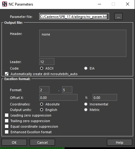 Figure 7: NC Parameters window
 -
Select “Enhanced Excellon format” and click “Close”
-
Name the drill file and save it in the same directory as your project
-
Select “Auto tool select” and “Repeat codes”
-
Click “Drill” to export the drill file
-
Click “Close” to return to the layout