Changing the Library Search Path in Cadence PCB Editor
Why would I need to change the library search path?
When creating a custom PCB footprint for a component, it is stored somewhere on your computer. In order for PCB Editor to find where a custom footprint is stored, the library search path must be changed so that PCB Editor knows where to look.
Note: In order for Design Entry CIS to find custom PCB footprints and associate them with schematic components, you also need to change the library search path in Design Entry CIS.
How do I change the library search path in PCB Editor?
- Save your custom footprints in the symbols folder on your computer. Depending on how Cadence is installed on your computer, the full path should be similar to:
C:\Cadence\SPB_17.2\share\pcb\pcb_lib\symbols
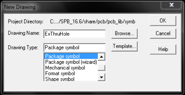
When creating a new footprint drawing, the New Drawing dialog box will show the default path (see Figure 1 below). If the path in the dialog box is different than the path above, use the dialog box path for the remainder of this tutorial.
Figure 1: New Drawing dialog box |
Also, note the exact name of the footprint. This will be needed later in order to reference it.
-
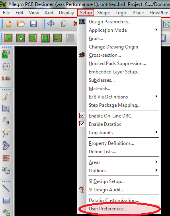
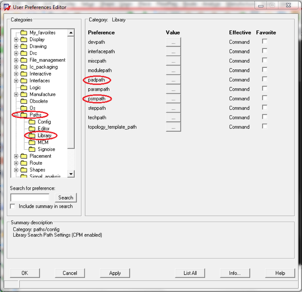
In PCB Editor, choose Setup > User Preferences… (see Figure 2). This will open the User Preferences Editor (see Figure 3).
Figure 2: User Preferences MenuFigure 3: User Preferences Editor -
In the User Preferences Editor (see Figure 3, above), choose the Paths > Library.
The padpath and psmpath lists where Cadence will search for padstack (.pad) and package symbol footprint (.psm) files on your computer.
-
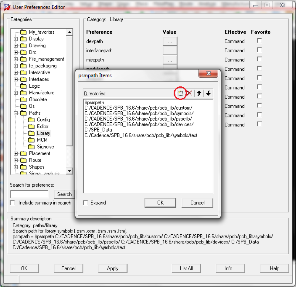
Click on the “…” button next to the padpath preference. A window similar to Figure 4 will appear.
Figure 4: psmpath Items Dialog Box -
Make sure the library search path from step 1 above is in the list. If it is not, click the new item button (circled in red in Figure 4) and add the full path to your footprint to the list. Do not delete any existing directories from the list. Click OK when finished.
-
Repeat steps 4 and 5 for the padpath, using the same path from step 1. It is recommended that padstacks (.pad) and package symbol footprints (.psm) be stored in the same folder to simplify usage. Click OK when finished to exit the User Preferences Editor.
-
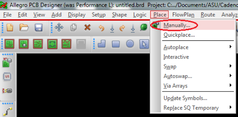
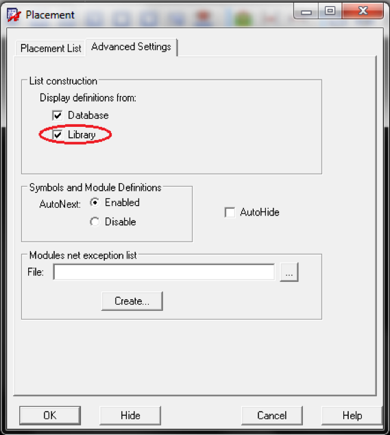
Finally, you need to confirm that the path was correctly updated to see your custom footprint. In PCB Editor, choose Place > Manually… (see Figure 5). This will open the Placement dialog box. Choose the Advanced Settings tab (see Figure 6).
Figure 5: Place Manually MenuFigure 6: Placement Dialog Box -
In the Advanced tab of the Placement dialog box (see Figure 6), ensure that the box next to Library is checked.
-
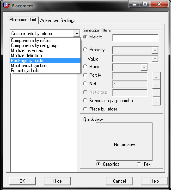
In the Placement dialog box, choose the Placement List tab and select Package symbols from the drop-down menu (see Figure 7).
Figure 7: Package symbols selected in the Placement dialog box -
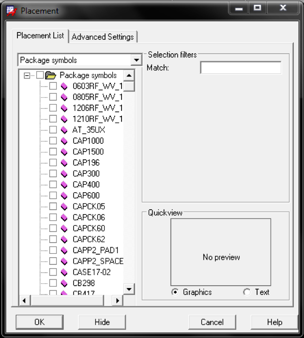
If your custom footprint shows up in the Placement List (see Figure 8), you have successfully updated the library search path. If it does not show up in the Placement List, re-check the above steps.
Figure 8: Footprints successfully linked to PCB Editor
Based on a tutorial written by Seana O’Reilly.
